This page chronicles the design, building, assembly and usage of an az/el mount for a 4.5 meter Paraclipse dish and associated equipment for EME.
Stacey E. Mills, W4SM
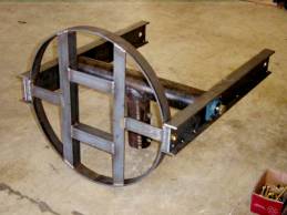
This is the beginning of the clothesline pole mount, based on a design by Robert Suding. The side arms are 4" wide I-beams hand made from 1/4" thick flat sheet steel. The "T" is 4" steel pipe. Steel discs with 1" nuts were welded into each end of the "T" bar to accept the two 1" hardened steel bolts which form the elevation axis. The axis pivots on 1" flange bearings mounted on the side arms. The mounting circle is 2 feet in diameter and was rolled from 1/4" x 2" steel.
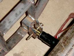
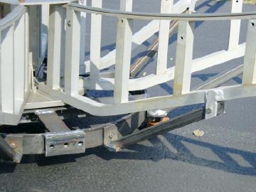
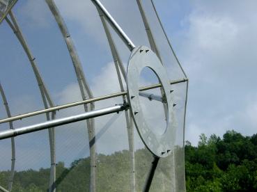
This is a close-up of the attachment point of the elevation actuator to the circular mounting ring.
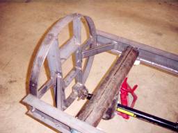
The main portions of the mount. Note the cross braces and the side I-beams
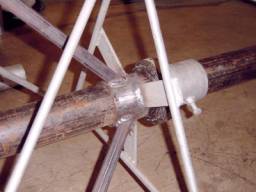
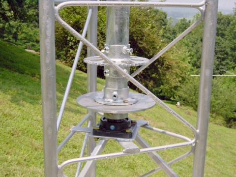
The mounting of the azimuth shaft at the top of the tower section. Note the large thrust bearing and the bracing for the tower loading.
The base of the azimuth shaft. A bearing mounts on the top surface of this plate and small shaft extends through the center hole for a positioning potentiometer or encoder.
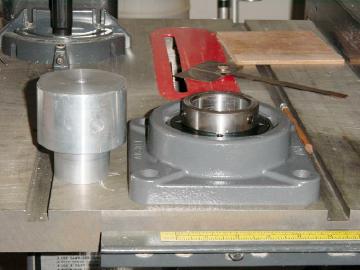
The bottom azimuth axis flange bearing is on the right. On the left is a machined aluminum adapter to allow the 3.5" aziumuth shaft to mount to the bearing. A hole in the bottom of this adapter serves as the attachment for the shaft of the azimuth axis potentiometer.
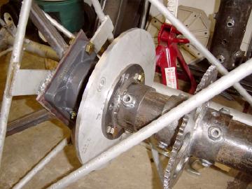
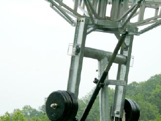
The lower end of the azimuth shaft. The drive sprocket is a 13" motorcycle sprocket. The aluminum plate below the sprocket (to the left) is the disc for a braking assembly which has yet to be designed.
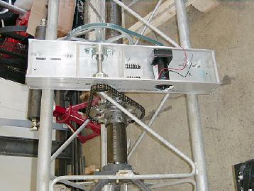
The azimuth drive unit was fabricated from aluminum plate. Output from a gear drive motor goes through two additional reductions to turn the azimuth shaft. One rotation takes about 6minutes ( 1 deg/sec).
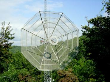
The mounting ring and the Paraclipse ribs. I wasn't satisfied with the Paraclipse mount (aluminum plate attached to ribs and ring) so I TIG welded aluminum ears to each of the ribs and made 8 "spider" supports to the main ring. This gives extra strength to the mounting.
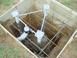
A four foot deep hole with re-bar for the base (over kill!). A 3" gray PVC conduit carries the drive controls and antenna coax. Note that the base has been carefully aligned to vertical and locked in place with a small amount of concrete around each of the three legs to prevent movement during the main concrete pour. If necessary, fnal adjustments can be made by shimming the leg mounts.
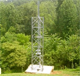
The tower goes up with the azimuth shaft, drive sprocket and braking disc.
Close-up of azimuth shaft, drive sprocket, brake disc and lower bearing. Note that all steel parts have been hot-dip galvanized for rust proofing.
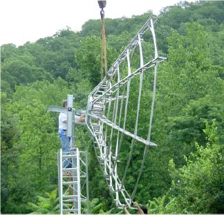
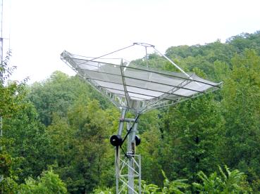
Bolting the dish to the mount with the help of a large sky hook and a helper on the ground. The mesh was not installed to protect it at this point. (Yes, I live on the side of a hill! It's not as bad as it looks. Elevation to the southwest is limited to 25 degrees and above.)
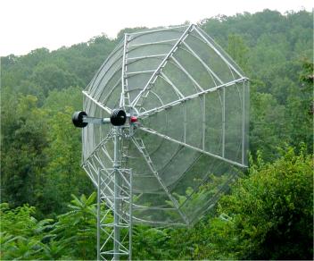
Dish with mesh installed and counter weights. Feed mount is next....
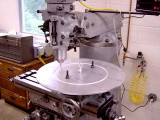
Machining the feed ring mounting from 3/8" aluminum
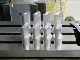
Machined inserts for the feed mount legs
Dish with feed ring mounted.
\
Close-up of feed ring. A tri-band (2.4 GHz, 1.2 GHz, 435 MHz) patch feed with mount to this ring. There is also room to mount downconverters, pre-amps, and relays as needed. On the list of "to do's" is an aluminum or plastic cover to fit over this assembly and protect from the weather.
Tied down for hurricane Isabel. Not quite vertical, but close enough to keep the cross-section down some. Winds hit over 65 MPH, but it held steady.
After hurricane Isabel passed by, I had time to fabricate two plexiglas boxes to protect the elevation bearings from direct exposure to water. In the pictures above this one, protection is provided by two red plastic cups and duct tape. The elevation positioning potentiometer/encoder will fit in the near enclosure.
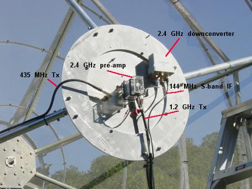
Here's the dish with the tri-band patch feed installed, first configuration. There are three coax lines going to the patch: 435 MHz Tx, 1.2 GHz Tx, and 144 MHz IF Rx from the S-band downconverter. Note that there is a separate pre-amp on S-band and the L-band notch filter is after the pre-amp. This created some desense from L-band Tx.
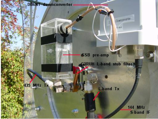
This closer view of the patch shows the current state of the "plumbing". The SSB pre-amp is housed in an acrylic case with a neoprene stopper sealing the coax and power feeds. The small white wire is 12V from the downconverter to power the pre-amp. Power to the downconverter is supplied by coax bias. The red cap-plug, to which the stub filter / pre-amp is tie wrapped is RHCP( LHCP after dish reflection) for L-band. This would be used for moonbounce receive with Tx on the opposite polarization. The bottom, partially hidden red cap plug (behind the L-band coax) is the RHCP (LHCP after dish reflection) for 435 MHz. Note that in this configuration the L-band notch filter comes before the pre-amp. This eliminated all L-band desense.
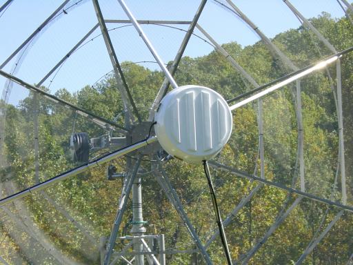
The pre-amp, downconverter and coax connectors are protected behind a plastic cover,made from an outdoor planter that was painted white.
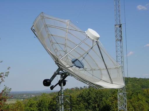
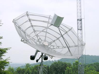
Here's the dish in satellite operational configuration!
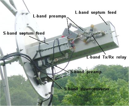
Following AO-40's battery incident, I decided to look into EME. The tri-band patch feed, while fine for satellites, didn't have the gain/circularity needed for EME. I built two septum feeds for L-band and S-band. These give GREAT circularity, extremely good Tx/Rx isolation, and improved reception of EME signals. I can now detect CW/SSB from the moon easily. At the moment I have only 50 watts on transmit, but can hear my CW signals under optimal conditions and easily see my echoes with WSJT.
Bottom view of septum feeds. S-band preamp (left) and S-band downconverter (right) are easily seen.
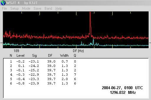
Averaged EME echo (red spike) on L-band running 50 watts at septum feed using "Echo mode" in WSJT 4 software. The -23.9 dB signal strength is relative to the noise level across the 2500 Hz passband. The blue graph is real-time, non-averaged signal.
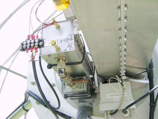
The septum feeds require a deeper cover, so this octagonal monster was fabricated out of sheet aluminum and pop rivets. There's plenty of room under there for S-band amps, X-band, etc.
The Small Tale of a LARGE Amplifier
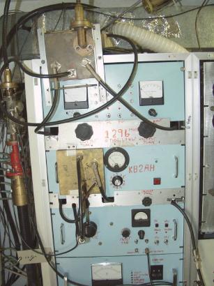
This is K2AH's well known 1296 amplifier, consisting of a 2-7289 cavity for a driver amp and two 6 -7289 cavities for the main amp unit. Note the 180 deg. splitter and combiner rings mounted externally. This amp served Tom well for many years but was in need of refurbishing after prolonged inactivity.
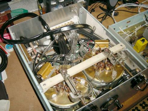
Here's the rebuild of the main amp showing the two 6-tube cavities. The 180 deg. ring splitter for input is at the back left. The manifolds for water and air cooling can be seen at the back right. Clear tubing is for water and black tubing is for air. Large flat cable connects to bias control unit. Filament transformers are located at the rear beneath the cooling tubing.
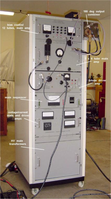
Here's the completely rebuilt amplifer. Note that the 180 deg. splitter ring is now internal. The 1/2" hardline from the external 180 deg. combiner is for testing only. I use a solid state brick to drive the 2-tube driver. This amp will easily manage 1400 watts on 1296, though I find it easier to run it at 1000 watts where it loafs along.
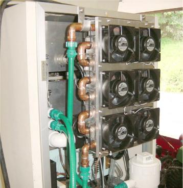
Here's the rear of the amp. showing the cooling system made from a hot water baseboard heater unit and 6 110 VAC muffin fans. The white PVC reservoir for distilled water is at the lower right. The main amp contains 3 PVC manifolds, one for water in, one for water out, and a larger one visible below these for air in to cool the main amp cathodes.
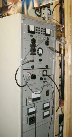
Here's a view of the amp in its functional location in an unfinished room behind my main shack. Bird wattmeters on the top measure output and "difference" from the 180 deg. combiner. 7/8" hardline runs directly to the dish feed.
...stay tuned for more pics and specs.
Stacey Mills, W4SM